A.P.D. breaks down Digitizing !!!
+4
bbf-falcon
slurm
69F100
twinturrbo406
8 posters
Page 1 of 1
 A.P.D. breaks down Digitizing !!!
... i spent some time working on digitizing the CV-385 port today, which is for the CV-1 cylinder heads, and i thought i'd walk you guys through the "Reverse-Engineering" phase of getting a new port into our CAD system, this is part of the very first steps in digitizing a port shape with our system ...
... the pic's show what we call a "Point Cloud" which is nothing more than a large amount of small points collected by the CMM, and you basically have to trace over the entire surface until you have a really nice coverage of points through the entire shape, as you do not want any small holes, this can cause problems later when the 3D Mesh phase begins ...
... this really is the hardest part of digitizing a port, once a good "Point Cloud" is in place, we'll move on to the next step and i'll post pic's of each step along the way so you guys will better understand what's involved in this process ...
... as you see the shape develop on the screen, it will become apparent the shape does not look correct ?? ... this is due to the fact that the CMM is programmed to the "Center" of the probe and that is the shape you'll be seeing until the "Point Cloud" is completed, afterwards i'll need to adjust the tool offset to the correct size and then you'll see the actual size and shape of the CV-385, but before then the port will look bloated in areas like the guide boss, and the floor wing, but this is perfectly normal, all you're seeing is the shape generated from the center of the probe, once the correct ".250" offset is entered, the shape will grow a total of .500 in size through out the entire shape ...
... i hope you guys enjoy the information, and if you have any questions, please feel free to ask, that's what we're here for ...


twinturrbo406- Posts : 45
Join date : 2010-12-22
Location : Tennessee
 Re: A.P.D. breaks down Digitizing !!!
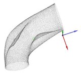
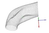
... ok, here we have pic's showing the CV-385's "Point Cloud" being refined using the Verisurf software which runs inside of MasterCam X6 ...
... and so everyone understands, the "Point Cloud" is gathered or recorded by simply tracing over the port's surface with the Master3DGage, which looks like a small robotic arm with a special port probe we had made that can reach all of the port's surface, it basically has a .500 diameter ceramic ball on the end of a steel shaft, and you're just dragging the ceramic ball over the surface, the entire surface that is, which obviouslt takes some time to get correct ...
... so after the complete "point Cloud" has been recorded, this now becomes the first stage of smoothing & refining the port surface, which is for now represented by the "Point Cloud" still ...
... you can see the "Point Cloud" has already become noticably smoother and more refined looking at this stage ...


twinturrbo406- Posts : 45
Join date : 2010-12-22
Location : Tennessee
 Re: A.P.D. breaks down Digitizing !!!
... and now we move on to the next 2 stageswhich is to crop the ends of the point cloud at the (Throat)(Intake Flange) and to generate the "3D Mesh" with the refined "Point Cloud" ...
... the first 2 pic's below illustrate what the "Cropping" process looks like, this process is to provide a nice clean cut edge to both ends of the port, as this will be very important once the "Splining" stage begins ...
... after the 3D Mesh is generated you'll notice that the ports size still looks incorrect, almost as if the shape were under a vacuum even, pulling the surface inward, this is most noticable in areas like the guide-boss or the floor-wing, this is due to the software using the center of the .500 diameter probe, which will be adjusted later to the correct tool offset of .250 diameter ...
... the Verisurf software generates the 3D Mesh by using a bunch of small and properly located triangulated shapes over the surface of the Point Cloud, if you look closely at the last 2 pic's below you'll see the triangulated shapes ...
... at this stage you'll notice some surface texture already present in the 3D Mesh, this is normal at this stage and will be addressed in the following steps, it is difficult to see that part from a Jpeg image, but i'm just refering to what you would see if you were in front of the computor performing this work ...


twinturrbo406- Posts : 45
Join date : 2010-12-22
Location : Tennessee
 Re: A.P.D. breaks down Digitizing !!!
... now the 4 step process begins ...
1. ("filter/refine/smooth 3DMesh")
2. ("Export to Back to Cloud & Filter Cloud")
3. ("Export Refined Cloud Back to 3D Mesh")
4. (filter/refine/smooth 3D Mesh")
... and depending on how good of a job you have done recording the original "Point Cloud" determines how many times you'll need to repeat this 4 step process ...
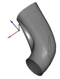
... so as the 4 step process begins you'll see a big difference in the surface of the 3D Mesh, and this process stops once the surface has a very nice uniform appearance, now if a problem occurs with the first 3D Mesh generation, you can go go back to the original point cloud and use the Master3DGage to record more point cloud data in the problem area to resolve the issue, but this is why you want to record a very dense point cloud over the entire surface before you generate the 3D Mesh the first time it will save you extra work later ...
... and notice the "Tool Offset" has not been corrected at this stage as the shape is still not to size, which will be very noticable once the offset is corrected ...


twinturrbo406- Posts : 45
Join date : 2010-12-22
Location : Tennessee
 Re: A.P.D. breaks down Digitizing !!!
... ok, now the "Tool Offset" will be corrected to .250 diameter, and this step will usually rough up the edges to the ends of the port that we previously cropped at the point cloud stage ...
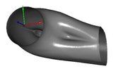
... the first pic below shows what the "Extend" function looks like, and this allows the 3D Mesh to then be cropped the same way the point cloud was cropped, as to restore the sharp edges needed at the ends of the port ...
... now the port is noticably larger, and is now to actual size, so if you were to need measurements or distances, the Verisurf/MasterCam software can be used for this and compared to the actual "Master Port" shape in the cylinder head ...


twinturrbo406- Posts : 45
Join date : 2010-12-22
Location : Tennessee
 Re: A.P.D. breaks down Digitizing !!!
... so now the 3D Mesh should be complete, as the first pic below shows, and the the "Auto Surfacing" function in Verisurf can be applied to the 3D Mesh, and if the the work was done correctly this is when you get to really see what the port shape looks like in reference to its true size & shape ...
... i like to use many different colors at this stage to really see what my CAD surface looks like, because sometimes you'll get a small wrinkle in the CAD surface, and certain colors can hide these small wrinkles ...
... the next step after review of the CAD surface is to "Spline" the CAD surface and this will be the final step in digitizing a new port shape with our system ...
... then location of the ports can begin, but for now i will post more pic's of the CV-385 CAD shape for you guys to take a look at ...


twinturrbo406- Posts : 45
Join date : 2010-12-22
Location : Tennessee
 Re: A.P.D. breaks down Digitizing !!!
Nice read keep them come always looking for more info and learning new things
69F100- BBF CONTRIBUTOR

- Posts : 5386
Join date : 2009-01-04
Age : 57
Location : Irwinville Ga.
 Re: A.P.D. breaks down Digitizing !!!
x2 I have some dove-c heads that need a good carving
slurm- Posts : 103
Join date : 2011-09-16
Age : 44
Location : north dakota
 Re: A.P.D. breaks down Digitizing !!!
That's some hi tech shit right there. Thx
bbf-falcon- Posts : 8995
Join date : 2008-12-03
Location : Jackson, Ohio
 Re: A.P.D. breaks down Digitizing !!!
Thanks Bill. Interesting stuff.
Frank
Frank

738drvr- Posts : 600
Join date : 2010-02-15
Age : 59
Location : Middle Tennessee
 Re: A.P.D. breaks down Digitizing !!!
I too have a pair of d0ve heads that could use some of this hi tec.porting. any ideas on pricing? Or how much r&d is still ahead?

fe50stang- Posts : 132
Join date : 2010-10-28
Age : 43
Location : beaverton Oregon
 Re: A.P.D. breaks down Digitizing !!!
bbf-falcon wrote:That's some hi tech shit right there. Thx
738drvr wrote:Thanks Bill. Interesting stuff.
Frank
... no problem, that's what i'm here for ...

twinturrbo406- Posts : 45
Join date : 2010-12-22
Location : Tennessee
 Re: A.P.D. breaks down Digitizing !!!
fe50stang wrote:I too have a pair of d0ve heads that could use some of this hi tec.porting. any ideas on pricing? Or how much r&d is still ahead?
... well, we are trying to catch up on some of the CNC porting work we have right now, and we are working on getting our fixture plates for some different platforms also, but as soon as they show up, we'll be test cutting the BBF iron head to see what we're looking at as far as cost, this stuff can take some time, i apologize ...
... but as soon as we make the first test cut, i'll be making some updates for you guys to check out and provide some CNC package pricing also ...

twinturrbo406- Posts : 45
Join date : 2010-12-22
Location : Tennessee
 Re: A.P.D. breaks down Digitizing !!!
it all may look good on paper , but how does the air like it ? do you have a program to simulate velocity ? or do you just have to cut then proceed to flow ?
Question for the old school iron porters out there what is your take on this ???? not tring to stir things up just curious
Question for the old school iron porters out there what is your take on this ???? not tring to stir things up just curious
_________________
coming soon x275 build .........
thanks to all my sponsors :
www.OakleyMotorsports.com
www.Induction-Solutions.com
www.bfevansraceparts.com
www.ultimateconverter.com
www.keithfulpmotorsports.com
 Re: A.P.D. breaks down Digitizing !!!
bruno wrote:it all may look good on paper , but how does the air like it ? do you have a program to simulate velocity ? or do you just have to cut then proceed to flow ?
Question for the old school iron porters out there what is your take on this ???? not tring to stir things up just curious
he's digitizing a port that he developed by hand porting, see his other post.

dfree383- BBF CONTRIBUTOR

- Posts : 14851
Join date : 2009-07-09
Location : Home Wif Da Wife.....
 Re: A.P.D. breaks down Digitizing !!!
dfree383 wrote:bruno wrote:it all may look good on paper , but how does the air like it ? do you have a program to simulate velocity ? or do you just have to cut then proceed to flow ?
Question for the old school iron porters out there what is your take on this ???? not tring to stir things up just curious
he's digitizing a port that he developed by hand porting, see his other post.
understand so he is reverse engineering the program so he can cnc ......
_________________
coming soon x275 build .........
thanks to all my sponsors :
www.OakleyMotorsports.com
www.Induction-Solutions.com
www.bfevansraceparts.com
www.ultimateconverter.com
www.keithfulpmotorsports.com
 Re: A.P.D. breaks down Digitizing !!!
bruno wrote:it all may look good on paper , but how does the air like it ? do you have a program to simulate velocity ? or do you just have to cut then proceed to flow ?
Question for the old school iron porters out there what is your take on this ???? not tring to stir things up just curious
... oh it likes the flow just fine ...
(CV-385) "4.400 bore"
.100 - 98.4
.200 - 175.5
.300 - 257.9
.400 - 328.7
.500 - 395.0
.600 - 448.4
.700 - 478.5
.800 - 480.4
.900 - 494.6
1.00 - 507.4
1.10 - 515.3

twinturrbo406- Posts : 45
Join date : 2010-12-22
Location : Tennessee
Page 1 of 1
Permissions in this forum:
You cannot reply to topics in this forum