Valvetrain Geometry
+3
bbf-falcon
c.evans
OldRedFord
7 posters
Page 1 of 1
 Valvetrain Geometry
I set up to check my valvetrain geometry this afternoon.
I am using the factory stamped steel rockers.
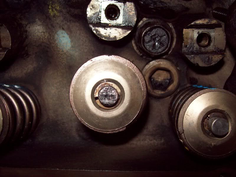
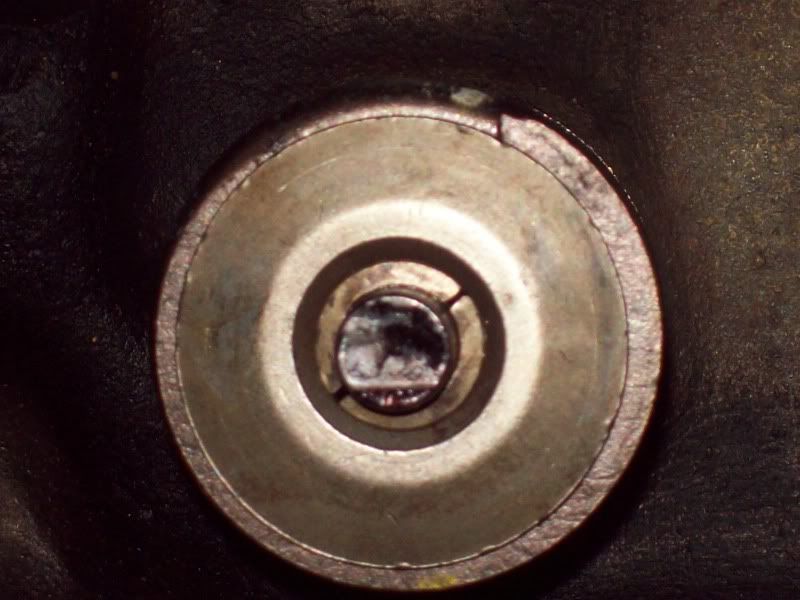
I coated the valve stems with a black marker, then rolled the engine over twice for each valve.
Wondered what you all thought.
Intake wipe pattern
Exhaust wipe pattern
Valve spring with lifter on the nose of the cam.
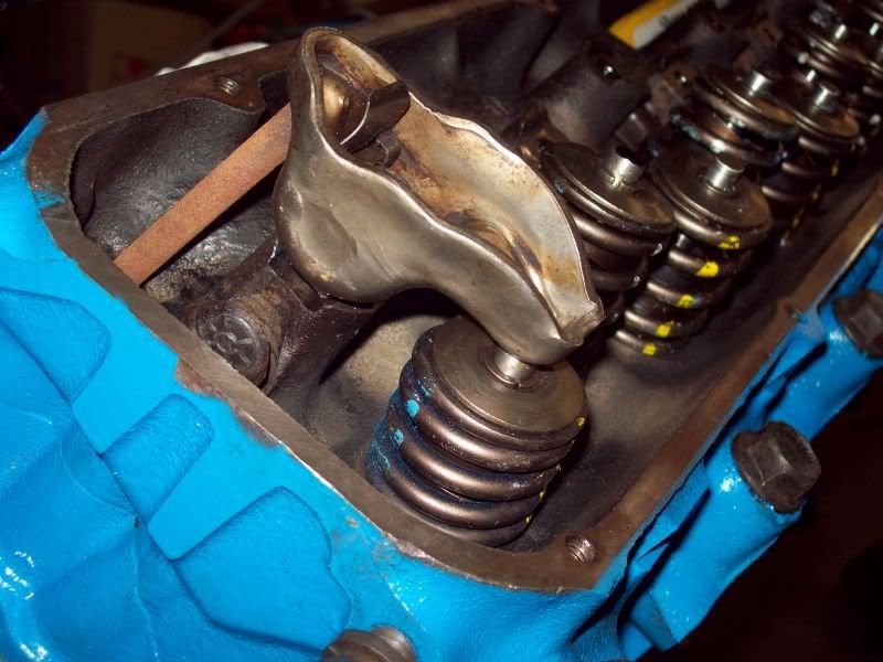
I used a factory push rod and a solid lifter. I had wondered if the factory push rods would be short with a bigger then stock cam, but didn't mill the heads or the block deck any.
I am using the factory stamped steel rockers.
I coated the valve stems with a black marker, then rolled the engine over twice for each valve.
Wondered what you all thought.
Intake wipe pattern

Exhaust wipe pattern

Valve spring with lifter on the nose of the cam.

I used a factory push rod and a solid lifter. I had wondered if the factory push rods would be short with a bigger then stock cam, but didn't mill the heads or the block deck any.
Last edited by OldRedFord on February 17th 2010, 2:01 am; edited 2 times in total (Reason for editing : Better details)

OldRedFord- Posts : 465
Join date : 2009-08-08
Age : 38
Location : Conyers GA
 Re: Valvetrain Geometry
Tim,
I don't mean to hurt your feelings, but I think things look terrible. You heads should have been rebuilt by a professional machine shop and given a new valve job. In the course of that work, the machine shop should have either replaced your valves,,,or at least reground the tips of your valves and gotten them all cleaned up and squared up. Your valves already have trenches dug in the tips, and if you run them that way, your asking for big trouble.
Charlie Evans
c.evans- BBF VENDOR SPONSOR

- Posts : 2260
Join date : 2008-12-03
 Re: Valvetrain Geometry
I coated the two valve tips with a black marker. Could it be the wipe pattern from the rocker arm on the valve tip making it look like it has a trench worn in it?
Ill try to get a picture with the marker cleaned off the tips.
Without the marker they look smooth, and show fingerprints.
Ill try to get a picture with the marker cleaned off the tips.
Without the marker they look smooth, and show fingerprints.

OldRedFord- Posts : 465
Join date : 2009-08-08
Age : 38
Location : Conyers GA
 Re: Valvetrain Geometry
I agree w/charlie. That valve tip looks Nasty 
bbf-falcon- Posts : 8995
Join date : 2008-12-03
Location : Jackson, Ohio
 Re: Valvetrain Geometry
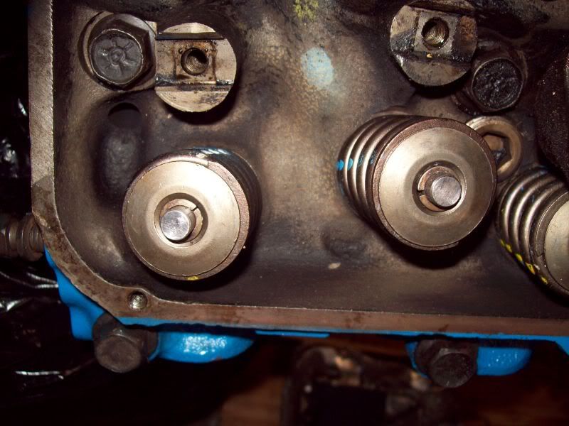
I dont mean to be hard headed but I am just not getting the whole part about the stems being chewed up.
This is a picture of the same two valves with the marker wiped off.
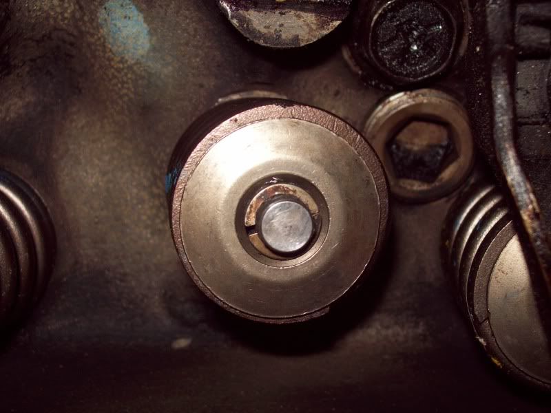
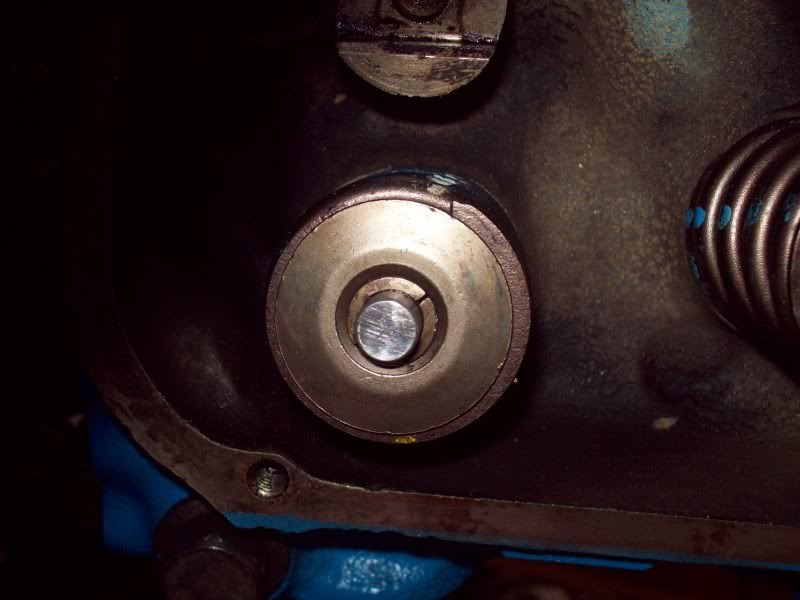
This is a picture of the same two valves with the marker wiped off.


OldRedFord- Posts : 465
Join date : 2009-08-08
Age : 38
Location : Conyers GA
 Re: Valvetrain Geometry
Tim,
All I can say is that it fooled me. There's a world of difference between the top set of pictures and the bottom set of pictures. The top set looked like the tips of the valves were pitted and worn. Seeing that rusty old pushrod didn't help either.
As for the geometry, I agree with Randy.
Charlie
All I can say is that it fooled me. There's a world of difference between the top set of pictures and the bottom set of pictures. The top set looked like the tips of the valves were pitted and worn. Seeing that rusty old pushrod didn't help either.
As for the geometry, I agree with Randy.
Charlie
c.evans- BBF VENDOR SPONSOR

- Posts : 2260
Join date : 2008-12-03
 Re: Valvetrain Geometry
Tim,
Try this procedure. With lifters, pushrods, valve springs all installed, and adjusted. Lay a small piece of Charmin toilet tissue between the tip of the valve and the rocker arm. Crank the engine over by hand and make sure that you go through one full cycle of opening and closing the valves, both intake and exhaust. Then "read" the Charmin tissue. If it is torn, you know the the rocker arm was dragging across the tip, and something needs to be done. If it is simply compressed, but not torn, then you know you have good geometry. That's an old NHRA Stocker trick.
Charlie
c.evans- BBF VENDOR SPONSOR

- Posts : 2260
Join date : 2008-12-03
 Re: Valvetrain Geometry
c.evans wrote:Tim,
Try this procedure. With lifters, pushrods, valve springs all installed, and adjusted. Lay a small piece of Charmin toilet tissue between the tip of the valve and the rocker arm. Crank the engine over by hand and make sure that you go through one full cycle of opening and closing the valves, both intake and exhaust. Then "read" the Charmin tissue. If it is torn, you know the the rocker arm was dragging across the tip, and something needs to be done. If it is simply compressed, but not torn, then you know you have good geometry. That's an old NHRA Stocker trick.
Charlie
138- Posts : 1593
Join date : 2009-08-19
 Re: Valvetrain Geometry
Ill try that tissue trick.
One other question I have...would using a solid lifter vs a dry hydraulic lifter make a difference?
One other question I have...would using a solid lifter vs a dry hydraulic lifter make a difference?

OldRedFord- Posts : 465
Join date : 2009-08-08
Age : 38
Location : Conyers GA
 Re: Valvetrain Geometry
OldRedFord wrote:Ill try that tissue trick.
One other question I have...would using a solid lifter vs a dry hydraulic lifter make a difference?
1. Yes, it will make a difference because the plunger cup will depress.
2. Measure the depth of the cup in your hydraulic lifter when it's just sitting out on the bench. Then measure the cup depth of your solid lifter. Hopefully they are close to the same. However,,,,,if the depths are way different, then that is in effect changing your pushrod length and will screw-up your geometery tests.
3. If they are different, then what I used to do was disassemble an old hydraulic lifter, identical to what I was running, and remove the guts, (little spring & etc.) make up a solid piece of tubing, of the correct length,,,,, and drop it in there and then reinstall the cup and snap ring. Then I had a hydraulic "checking" lifter identical to what I was running, but it would stay solid and act like a pumped up lifter would in operation.
Hope this helps,
Uncle Charlie
c.evans- BBF VENDOR SPONSOR

- Posts : 2260
Join date : 2008-12-03
 Re: Valvetrain Geometry
c.evans wrote:Tim,
Try this procedure. With lifters, pushrods, valve springs all installed, and adjusted. Lay a small piece of Charmin toilet tissue between the tip of the valve and the rocker arm. Crank the engine over by hand and make sure that you go through one full cycle of opening and closing the valves, both intake and exhaust. Then "read" the Charmin tissue. If it is torn, you know the the rocker arm was dragging across the tip, and something needs to be done. If it is simply compressed, but not torn, then you know you have good geometry. That's an old NHRA Stocker trick.
Charlie
Thanks Charlie learned something new to night never thought about using the tissue to check the valve train before but make real good sense .
Sorry Tim don't want to high jack your tread but Charlie would this work on roller tip rockers to.
Jim

69F100- BBF CONTRIBUTOR

- Posts : 5386
Join date : 2009-01-04
Age : 57
Location : Irwinville Ga.
 Re: Valvetrain Geometry
'Er, after looking at the pics, what does the tip face of your used rockers look like??
 Re: Valvetrain Geometry
There is a definite worn spot on the rocker where it contacts the valve, but smooth and not deep.
Thanks Charlie for the info.
Thanks Charlie for the info.

OldRedFord- Posts : 465
Join date : 2009-08-08
Age : 38
Location : Conyers GA
 Re: Valvetrain Geometry
Jim,
That old stocker trick should be useless on a roller rocker arm, because the roller will just roll and make a depression. If for some reason it did tear the tissue, I'd say you've got big problems.
With a roller tip rocker arm, use can use machinist dykem or a felt tip marker. You want the travel to be on the center 1/3rd of the valve stem tip, starting on the inside closest to the rocker stud, and traveling outward towards the spark plug side of the head, and then back to the inside. Once you get that kind of travel pattern, you are acceptable. However, if you can finesse your pushrod length, and the rocker's up/down position on the stud....to narrow and reduce the amount of travel to the center 1/5th of the valve stem tip, then you are even better.
Hope this helps,
Charlie Evans
c.evans- BBF VENDOR SPONSOR

- Posts : 2260
Join date : 2008-12-03
 Re: Valvetrain Geometry
As far as new push rods, would Comp Cams 7834-16 push rods be a good choice? I am not running any crazy stiff springs or a huge cam.

OldRedFord- Posts : 465
Join date : 2009-08-08
Age : 38
Location : Conyers GA
 Re: Valvetrain Geometry
Thanks for the info Charlie sorry about butting in Tim on your tread
Jim
Jim

69F100- BBF CONTRIBUTOR

- Posts : 5386
Join date : 2009-01-04
Age : 57
Location : Irwinville Ga.
 Similar topics
» Valvetrain Geometry
» No oil getting to driver side valvetrain
» rocker geometry
» Rocker Geometry
» Determining the correct valve geometry??
» No oil getting to driver side valvetrain
» rocker geometry
» Rocker Geometry
» Determining the correct valve geometry??
Page 1 of 1
Permissions in this forum:
You cannot reply to topics in this forum